EN
EN
CAN-BUS Data Transmission System Teaching Board
OEM Accept OEM Accept ODM
Application Training Institute & School
Customization Size / Appearance / Material...
Function Automotive Training
Warranty 2 years
Package Wooden Box
Technical Support Software / Instruction manual / Video / Technician guidance
Shipping Way By Sea / Air / Express
Certification ISO9001 / GPSR / Copyrights
- Overview
- Recommended Products
CAN-BUS Data Transmission System Teaching Board
I. Product Overview:
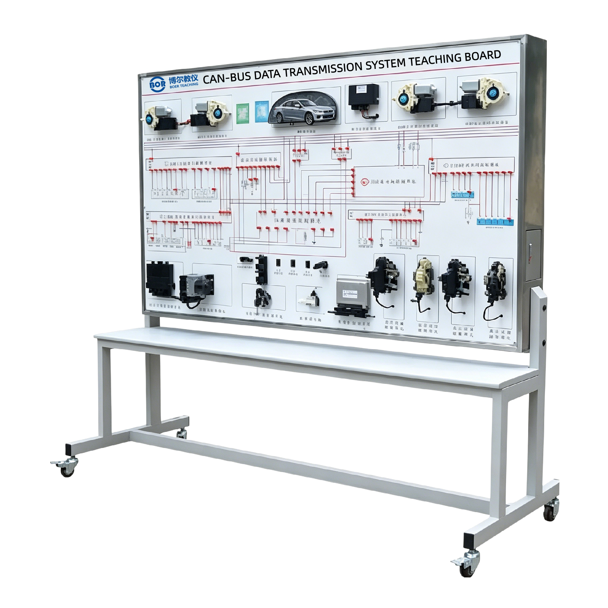
This teaching board uses components from the original automotive CAN-BUS system, realistically demonstrating the structure of the CAN-BUS system. It can demonstrate the working process and principles of CAN-BUS data transmission. Suitable for practical training in the construction and maintenance of CAN-BUS systems, it meets the teaching needs for the structure, working principles, fault setting, and diagnosis of CAN-BUS systems.
II. Component Structure:
The teaching board mainly consists of a rearview mirror, left front window motor, right front window motor, left front lock block, right front lock block, left rear window motor, left rear lock block, right rear window motor, right rear lock block, instrument cluster, rearview mirror switch, window switch, ignition switch (with anti-theft function), ignition coil, engine control unit, diagnostic connector, crankshaft position sensor, fuel injectors, transmission control unit, transmission actuators, ABS control unit, ABS sensor, training panel, ignition switch, ignition key, DC12 power supply, and a movable platform.
III. Functional Features:
1. The CAN-BUS system is fully equipped with all components, demonstrating its complete structure.
2. The CAN-BUS system functions normally, demonstrating the data transmission status of the powertrain and comfort systems, fully showcasing its working process and principles.
3. A complete engine ignition and fuel injection system is included, displaying the engine ignition and fuel injection status.
4. The training platform panel features color-printed circuit diagrams and working principle illustrations, allowing trainees to visually compare the diagrams and physical components to understand and analyze the CAN-BUS system's working principle.
5. The training platform panel is equipped with testing terminals, allowing direct testing of the electrical signals (resistance, voltage, current, frequency, etc.) of the CAN-BUS system's electrical components.
6. The training platform is equipped with a diagnostic connector, which can be connected to a dedicated or universal automotive decoder to perform self-diagnostic functions such as reading fault codes, clearing fault codes, and reading data streams from the CAN-BUS system's electronic control system.
7. It uses a DC 12V power supply, reducing charging hassles, and the power supply has short-circuit protection.
8. The equipment adopts a mobile platform structure with locking swivel casters for convenient teaching; the overall platform...
9. Automotive models are selectable;
IV. Technical Specifications:
1. Overall Reference Dimensions: 2000×850×1860mm (Length×Width×Height);
2. External Power Supply: AC 220V±10% 50Hz;
3. Operating Voltage: DC 12V;
4. Operating Temperature: -5℃~+50℃;