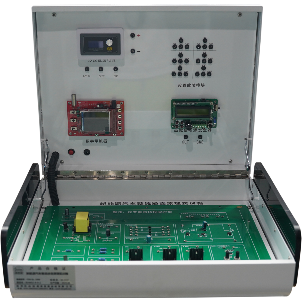
New Energy Rectification and Inversion Circuit Connection
Delivery: EXW Guangzhou
Shipping Way: By Sea / Air / Express
Certification: ISO / GPSR / Copyrights / Patents...
OEM Service: Accept OEM Accept ODM
Customization: Logo / Size / Appearance / Material...
Technical Support: Software / Manual / Video / Technician
- Overview
- Recommended Products
- Half-wave rectifier circuit connection
- Full-wave rectifier circuit connection
- Chip-based full-wave rectifier circuit connection
- Transformer and transistor inverter circuit connection
- Chip-controlled inverter circuit connection
- Field-effect transistor (FET) inverter circuit connection
- Half-wave rectifier circuit using capacitors and diodes
- Full-wave rectifier circuit using capacitors and diodes
- PWM-controlled full-wave rectifier circuit using mainstream rectifier chips
- Transformer and transistor inverter circuit
- Chip-controlled inverter circuit
- Inverter circuit using diodes, capacitors, and field-effect transistors
- Integration with other circuit systems or user-designed circuits
- One aluminum box
- One universal base plate
- One set of electronic components
- One set of standard component cards
- One set of breadboard wires
- One set of plug-in connection wires
- One protective circuit set
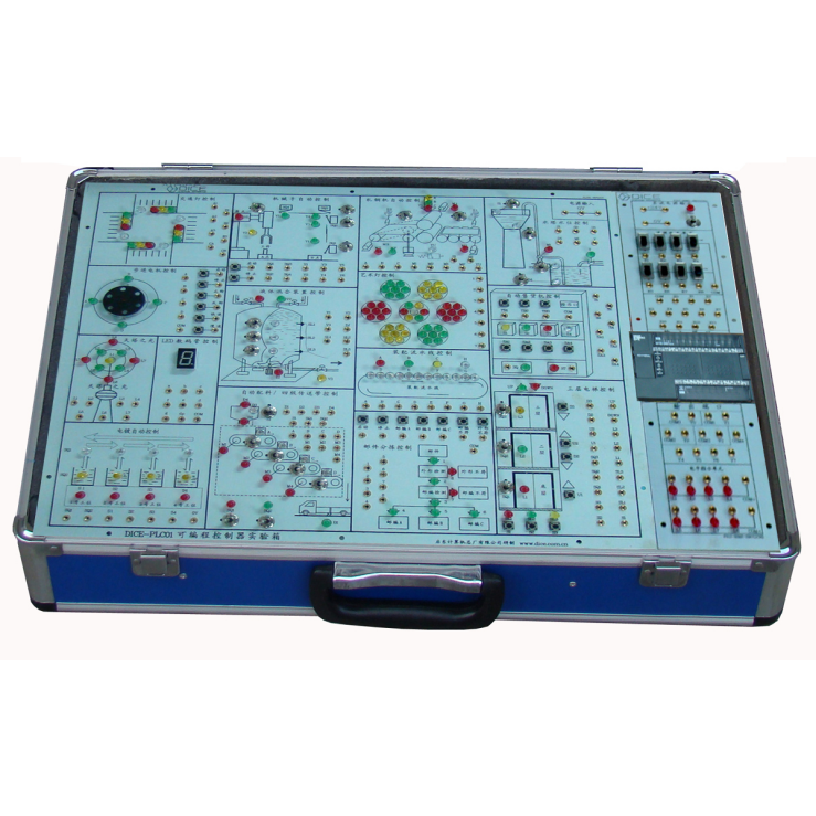
I. Product Features
The experimental components and modules are mounted on plug-in sockets. The reference circuit can be directly connected to the physical layout using the instruction manual. Each component corresponds one-to-one with the diagram, making the learning process intuitive, engaging, and highly participatory.
All components are housed in a durable aluminum box structure equipped with plug-in wiring sockets, allowing easy expansion or addition of more complex circuit components in the future.
The components used in this product are mainstream in the market and compatible with a variety of electrical instruments. They can form the fundamental circuits used in technician-level electrical experiment teaching and demonstration.
A standardized plug-in connector design is adopted, with different colors for easy distinction. Each component socket features a hollow rivet jack for convenient plug-in operation. Direct plug-in connectivity ensures circuit nodes maintain equal potential, simplifying troubleshooting and making circuit observation clear and straightforward.
If components are damaged due to operational error, they can be easily replaced, significantly improving the reusability and longevity of the equipment.
II. Equipment Requirements
The system can be used to build circuits with various functions according to instructional needs, ensuring reliable performance during teaching demonstrations.
The supporting plate is made of a high-quality PCB board with a rectangular layout, measuring not less than 30 cm × 30 cm and a thickness of at least 1.6 mm, ensuring durability during repeated plugging and unplugging operations.
The overall structure adopts a high-strength aluminum box design, approximately 35 cm × 35 cm in size, with reinforced framing around the edges. The hinge features a flat opening design that allows both sides to open fully. The interior is lined with black velvet fabric and includes sewn pockets for convenient component storage and organization.
The connecting wires are insulated with environmentally friendly materials and equipped with plug-in terminals, enabling quick and reliable connections on the universal board.
A detailed training guide (provided in both paper and high-definition electronic formats) offers complete instruction for conducting connection experiments. The guide includes product descriptions, physical structure diagrams, usage methods, connection exercises, and explanations of working principles.
The training guide covers six key tasks:
III. Basic Experimental Circuits
The platform supports the construction and testing of the following circuits:
IV. Basic Configuration
Each training kit includes:
V. Supporting Teaching Resources:
Free training, product manuals, courseware, worksheets, maintenance manuals, and operation videos are provided.