EN
EN

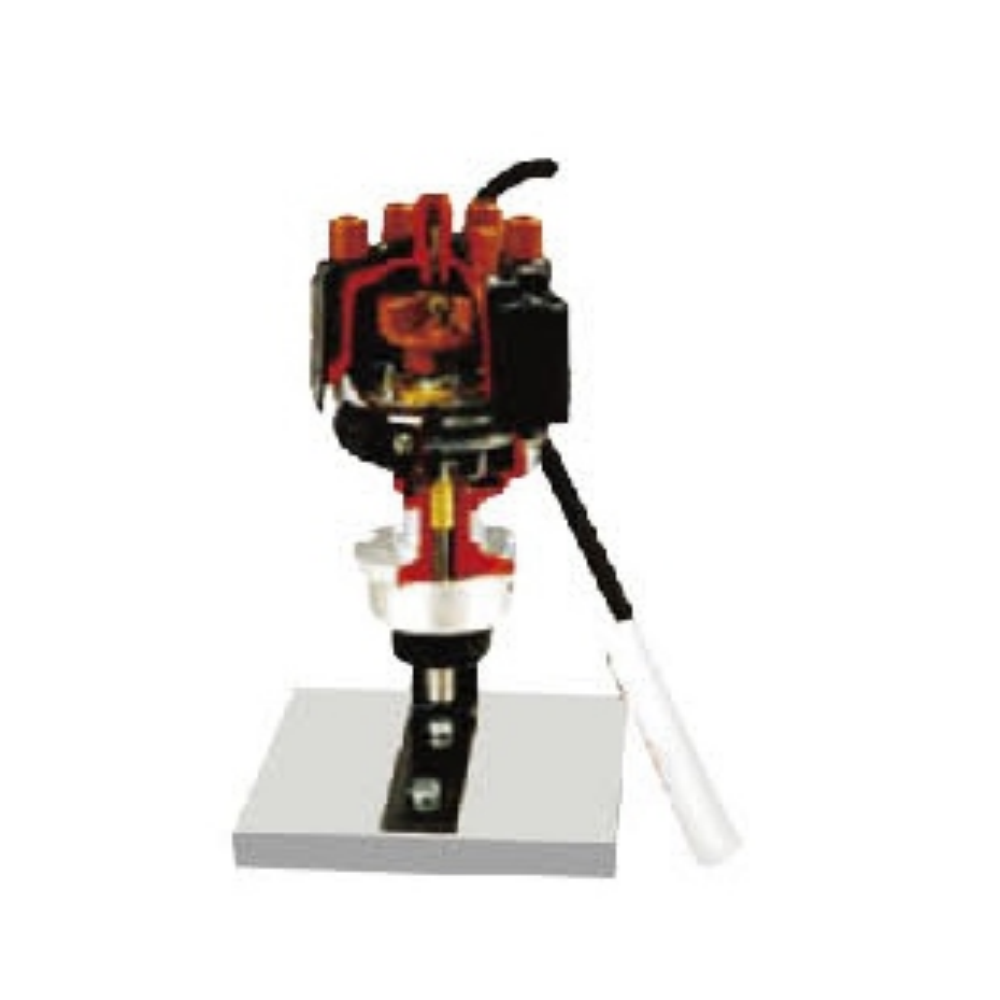
Anatomical model of a magnetoelectric distributor
Delivery: EXW Guangzhou
Shipping Way: By Sea / Air / Express
Certification: CE/ ISO / GPSR / Copyrights / Patents...
OEM Service: Accept OEM Accept ODM
Customization: Logo / Size / Appearance / Material...
Technical Support: Software / Manual / Video / Technician
- Overview
- Recommended Products
Product Overview:
This is a teaching model based on the professional dissection and color-coded painting of a realistic induction ignition distributor assembly. It visually demonstrates the internal structure, signal generation principle, and ignition advance adjustment mechanism of a magnetic induction contactless distributor. It is a core teaching tool for vocational/higher vocational automotive repair programs and training institutions.
Features:
1. Dissects the entire distributor assembly (with complete accessories), showcasing all components and comprehensively displaying the assembly's internal and external structure.
2. The dissection and color-coded painting of different sections clearly reveal the mechanical structure of the internal and external components and their assembly relationships.
3. The equipment base (with shock-absorbing pads) is made of 1.5mm cold-rolled steel sheet, stamped and coated. The shock-absorbing pads are secured to the base with M6*4 screws.
Training Projects:
I. Structural Cognition Training
Identify the components of an induction distributor:
Distributor cover, ignition head
Magnetic induction signal generator (signal rotor, induction coil, iron core, permanent magnet)
Centrifugal ignition advance mechanism
Vacuum ignition advance mechanism
Understand the installation position and transmission relationship of each component.
Compare the structural differences between Hall effect, photoelectric, and induction ignition signal generators.
II. Working Principle Demonstration Training
Manually rotate the distributor shaft and observe the relative motion between the signal rotor and the coil.
Understand the process of magnetic flux change → generating an induced voltage signal.
Demonstrate the changes in signal frequency and amplitude with changes in rotational speed.
Observe the operation of the centrifugal advance mechanism as rotational speed changes.
Observe the operation of the vacuum advance mechanism as vacuum level changes.
III. Ignition Advance Mechanism Operation Training
1. Centrifugal Ignition Advance Mechanism
2. Vacuum Ignition Advance Mechanism
IV. Fault Simulation and Analysis Training
Simulate the impact of open circuits and short circuits in the induction coil on the ignition signal.
Simulate the impact of a dirty signal rotor and excessive air gap on the signal.
Simulate the impact of centrifugal/vacuum mechanism jamming and spring failure on ignition timing.
Analyze the causes of the faults based on the observed phenomena and write out the diagnostic approach.
V. Measurement and Testing Training (Applicable to models with test terminals)
Measure the resistance of the induction coil using a multimeter.
Observe the output signal waveform and voltage using an oscilloscope/multimeter.
Measure the air gap between the signal rotor and the iron core.
Assess the technical condition of the signal generator.
VI. Disassembly and Assembly Training
Disassemble the distributor housing, signal generator, and advance mechanism according to specifications.
Understand the internal assembly relationships and positioning marks.
Reassemble in sequence, checking for smooth rotation and normal mechanism operation.