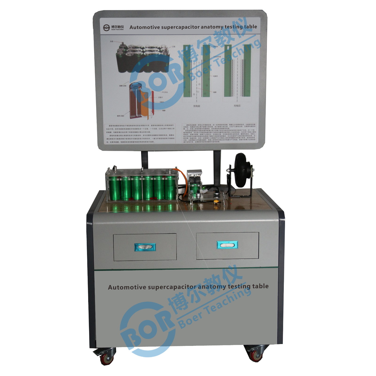
Automotive Supercapacitor Dissection Training Platform
Minimum Order : 1 Set
Warranty: 2 years
Delivery: EXW Guangzhou
Shipping Way: By Sea / Air / Express
Certification: ISO / GPSR / Copyrights / Patents...
OEM Service: Accept OEM Accept ODM
Customization: Logo / Size / Appearance / Material...
Technical Support: Software / Manual / Video / Technician
- Overview
- Recommended Products
Product Overview:
This product utilizes a supercapacitor bank and energy management system for new energy vehicles to demonstrate the system's structure, control (operation) principles, and the charging and discharging characteristics of supercapacitors. It is suitable for teaching experiments to understand and verify supercapacitor bank and energy management systems.
Features:
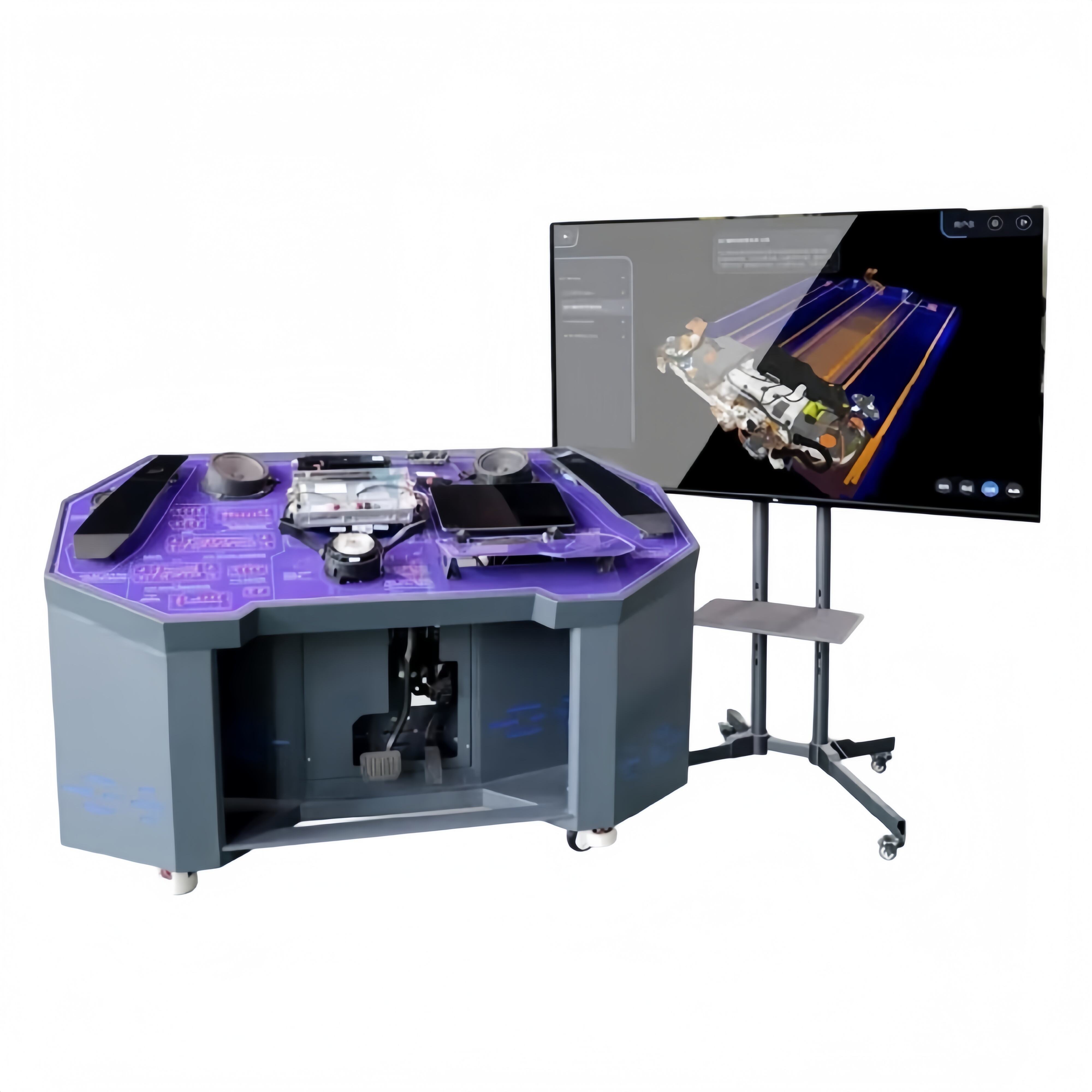
1. This equipment fully demonstrates the supercapacitor energy management system, dynamically simulating the energy flow direction and operating status under various working conditions.
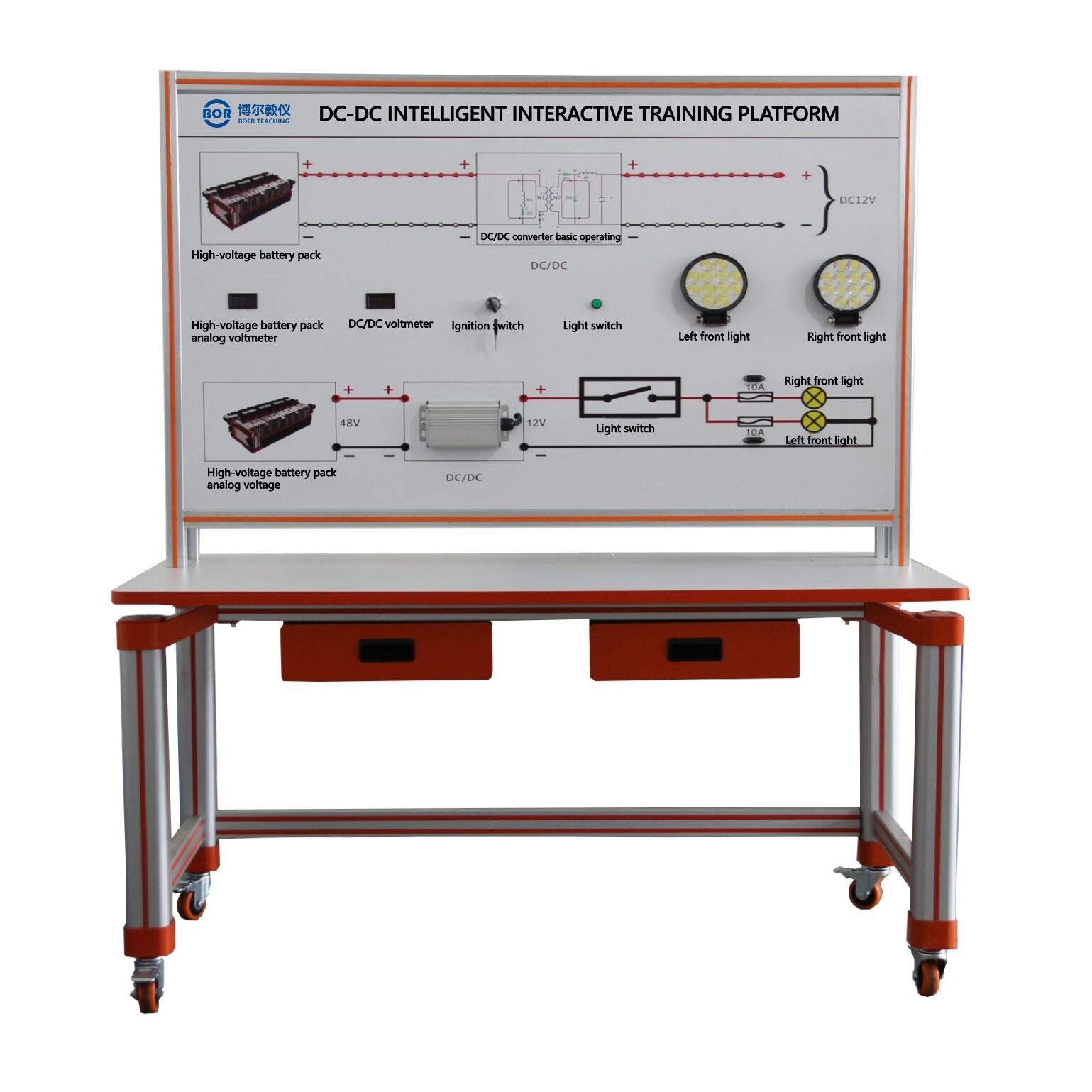
2. The operation panel uses 4mm thick aluminum composite panel, printed with a permanent, color-coded electronic circuit diagram and operating principle illustration; students can intuitively compare the system's structural principle diagram and the physical components to understand and analyze the system's operating principles.
3. It includes an ignition switch, supercapacitor bank, controller (operator), battery pack, rectifier bridge, DC/DC electronic circuit, and discharge device.
4. The system manages the supercapacitor battery pack via a CAN bus, comprehensively demonstrating the operating characteristics of the supercapacitor battery management system.
5. The voltage of individual battery cells is adjusted via the load control (operation) device; the voltage, temperature, total voltage, SOC, and voltage balance status of each battery cell are displayed on the host computer; the total voltage, charging and discharging current of the battery pack are also displayed on the host computer.
6. The system has a self-diagnostic function, which alarms and displays abnormal phenomena. System function values can be set and calibrated.
7. The equipment frame structure is constructed using two types of integrated all-aluminum profiles: 40mm×40mm and 40mm×80mm. It is oil-resistant, corrosion-resistant, and easy to clean. The tabletop is 40cm wide and covered with 32mm thick colored high-density composite board, which is durable and rust-free. It has four self-locking casters for easy movement.
8. Accompanying experimental manuals and other teaching drawings and training documents provide a complete explanation of the operating principles, experimental projects, fault settings and analysis, and other key points.
9. Mechanical Assembly and Fitter Assembly Virtual Simulation System: This system is developed based on Unity3D, offering 6 levels of graphics quality. It includes features such as speed reducers, shaft system design and virtual disassembly/assembly, common mechanical mechanism design and simulation, a mechanism resource library, and classic mechanical mechanisms (virtual disassembly/assembly of gasoline engine). The system is a unified whole, not a standalone resource.
10. Speed Reducer Design and Virtual Disassembly/Assembly Interface: Options include worm gear bevel gear speed reducers, two-stage unfolded cylindrical gear speed reducers, bevel-cylindrical gear speed reducers, coaxial cylindrical gear speed reducers, bevel gear speed reducers, and single-stage cylindrical gear speed reducers.
11. Worm Gear Bevel Gear Speed Reducer: The system automatically plays assembly content upon entry, with text explanations for each step in the video.
12. Two-stage unfolded cylindrical gear reducer: After entering the system, the content will be played in video format. The video content should include: part name (scan the QR code to view the part name), disassembly and assembly demonstration (including disassembly and assembly), and virtual disassembly and assembly (including the whole, low-speed shaft, medium-speed shaft, high-speed shaft, cover, and base).
13. Bevel cylindrical gear reducer, coaxial cylindrical gear reducer, bevel gear reducer, single-stage cylindrical gear reducer: After clicking to enter, you will be automatically redirected to the images interface. The models are all three-dimensional (3D) models. Clicking on the parts will reveal the part names. It can be rotated, zoomed in, zoomed out, and translated 360°. The entire reducer can be disassembled and reassembled using the part displacement function. You can also use the home button to return to the initial state of the reducer. The bevel gear reducer and single-stage cylindrical gear reducer have added a cross-section insertion function, allowing you to freely drag the cross-section to view the internal structure of the reducer.
14. Shaft system design and virtual disassembly/assembly interface: Optional features include parts identification, disassembly/assembly demonstrations, and hands-on practice.
15. Parts Identification: Includes 3D models and names of helical gears, end caps without holes, couplings, coupling keys, shafts, gear keys, end caps with holes, bushings, and deep groove ball bearings. Any part can be disassembled and assembled 360°. Demonstration: Two built-in examples; when the mouse hovers over a part (except for the base and bearing housing), the part automatically zooms in and displays its name. Disassembly and assembly buttons are provided, and the system automatically completes the disassembly and assembly of the shaft system. The 3D scene can be rotated, zoomed in, zoomed out, and translated 360°.
16. Hands-on Practice: 3D parts are neatly arranged on the desktop. Students manually select the corresponding parts and move them onto the shaft system. Parts can only be assembled when the placement order and position are correct. A restart button is provided for students to repeat the virtual experiment. When the mouse cursor hovers over a part (excluding the base and bearing housing), the part automatically enlarges and displays its name.
17. Common Mechanical Mechanism Design and Simulation: Optional four-bar linkage design and analysis, Type III crank-rocker mechanism design and analysis, offset crank-slider mechanism design and analysis, crank-oscillating guide rod mechanism design and analysis, four-bar linkage trajectory synthesis, eccentric direct-acting roller pushrod cam, and concentric direct-acting flat-bottom pushrod cam.
18. Each mechanism should be able to display corresponding functional values, which will be automatically calculated by the system. Motion simulation and automatic drawing of bending lines are also possible.
19. The mechanism resource library includes 11 types of planar linkage mechanisms, 5 types of cam mechanisms, 6 types of gear mechanisms, 8 types of transmission mechanisms, 11 types of clamping mechanisms, 6 types of gear train mechanisms, and 8 other mechanisms (mechanical equipment simulation).
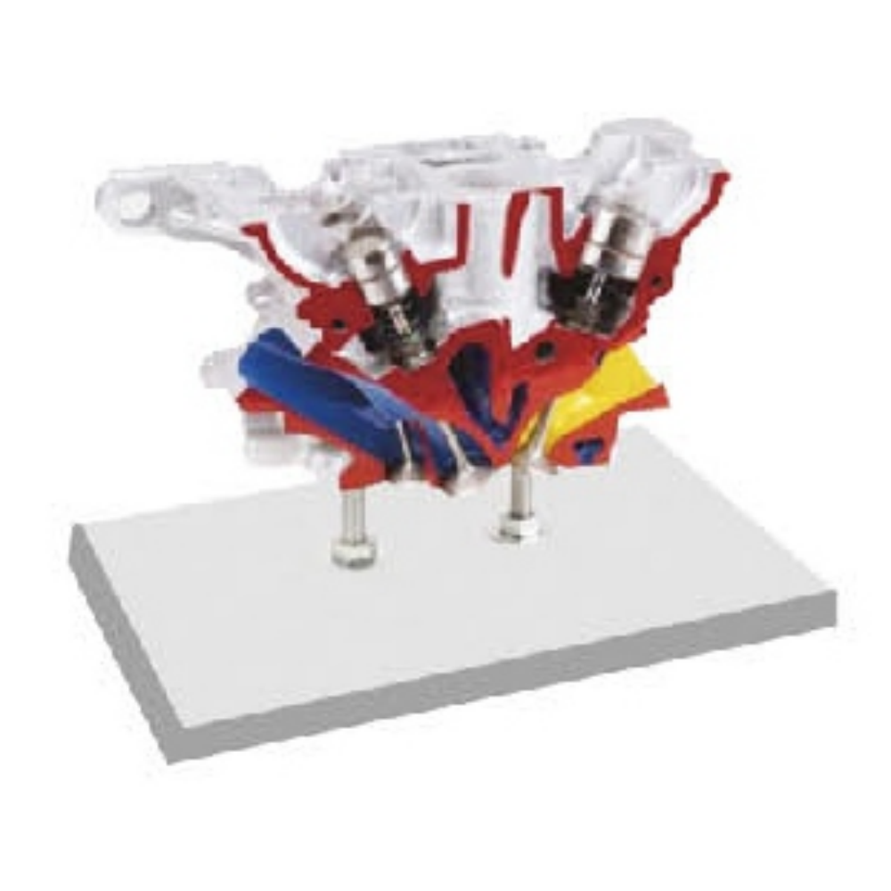
20. Virtual disassembly and assembly of gasoline engines includes crankcase assembly/disassembly demonstration, crankcase virtual assembly, valve train assembly/disassembly demonstration, and valve train virtual assembly.
21. Both the crankcase and valve train assembly/disassembly demonstrations include buttons for disassembly, assembly, restart, and disassembly/view. Moving the mouse over a part automatically zooms in and displays its name. The system automatically completes the disassembly and assembly of the crankcase and valve train structure. Using the disassembly/view button automatically displays an exploded view of the crankcase or valve train 3D model, allowing for 360° rotation, zooming, and translation.
22. In both the crankcase and valve train virtual assembly, the 3D parts are neatly arranged on the desktop. Students manually select the corresponding parts and move them onto the mechanism. Parts can only be assembled when the order and position are correct. A restart button is provided for students to easily repeat the virtual experiment. Moving the mouse over certain parts automatically displays their names.
Technical Specifications:
Dimensions: 1200 × 800 × 1500mm (L × W × H)
Operating Power Supply: AC220V±15% 50Hz
Operating Temperature: -20°C ~ 50°C