Interactive teaching module for the whole vehicle control system of pure electric vehicles
Minimum Order : 1 Set
Warranty: 2 years
Delivery: EXW Guangzhou
Shipping Way: By Sea / Air / Express
Certification: ISO / GPSR / Copyrights / Patents...
OEM Service: Accept OEM Accept ODM
Customization: Logo / Size / Appearance / Material...
Technical Support: Software / Manual / Video / Technician
- Overview
- Recommended Products
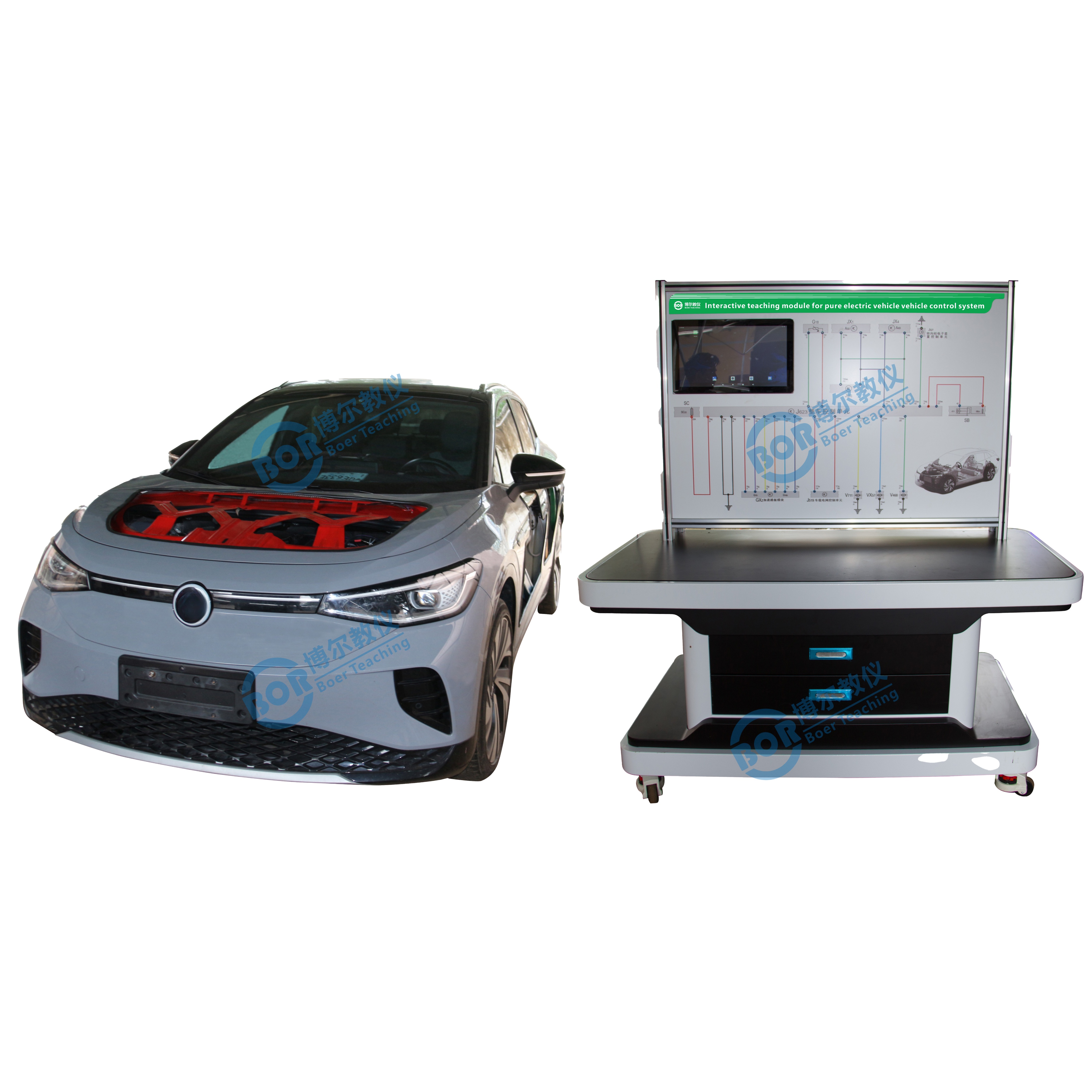
Product Overview:
The Pure Electric Vehicle Control System Interactive Training Platform is built using real components from a pure electric vehicle control strategy system. It includes the battery and management system, motor and control system, on-board charging system, vehicle controller (VCU) and control system, power conversion system (AC-DC module, DC-DC module, DC-AC module), and high-voltage safety system. It realistically demonstrates the structure, principles, and working process of the electric vehicle control strategy system, showcasing its power performance, reliability, and safety performance.
It enables control strategy demonstration and verification operations, including start-up mode, normal driving mode, energy management strategy, safety control strategy, and control strategies under other conditions, and performs detection, analysis, and diagnosis of the control strategies.
Features:
1. It can demonstrate the complete structural composition of a pure electric vehicle control strategy, including the permanent magnet synchronous motor control, battery management, VCU control, on-board charger, power conversion system, and high-voltage safety system.
2. Install actual components of a pure electric vehicle, including the battery and management system, motor and control system, on-board charging system, vehicle controller (VCU) and control system, power conversion system (AC-DC module, DC-DC module, DC-AC module), and high-voltage safety system, realistically demonstrating the structure, principles, and operation of the electric vehicle control strategy system.
3. Install devices for various driver operations, including gear control, accelerator pedal, and brake pedal. Demonstrate the various intentions of the driver's operations and how they interact with the electric vehicle control system.Show normal operation of the electric drive power system during acceleration, deceleration, braking, and energy recovery.
4. Demonstrate and verify the control strategy, including start-up mode, normal driving mode, energy management strategy, safety control strategy, and control strategies under other conditions, and perform detection, analysis, and diagnosis of the control strategies.
5. Lithium-ion battery and management system (BMS): Perform real-time monitoring of power battery parameters, fault diagnosis, SOC estimation, short-circuit protection, insulation detection, charge/discharge control, equalization, and other functions, and exchange information with the on-board charger with CAN communication via CAN bus.
6. The power battery pack for pure electric vehicles (power battery: 24 single-cell 3.2V 50Ah lithium iron phosphate batteries in series) includes a battery management system (BMS) comprising: voltage, temperature, and current acquisition modules, and a main control module. The main control module communicates with other modules via a CAN network, providing a direct understanding of the power battery pack technology.
7. The power battery pack, Hall current sensor, charging relay, discharging relay, pre-charge relay, total positive relay, and total negative relay are all equipped with detection ports, enabling real-time monitoring of electrical signals of system circuit components, such as resistance, voltage, current, and frequency signals.
8. The BMS battery management system features passive balancing functionality and switch control protection (single-cell disconnection, short circuit, overvoltage, undervoltage, overcurrent, and overtemperature). It communicates with the on-board charger via CAN, controlling the on-board charger's operation and estimating SOC (State of Charge).
(1) It features single-cell voltage data acquisition, total voltage data acquisition, current acquisition, and temperature acquisition.
(2) It has comprehensive fault level alarm functions, including voltage, current, and temperature fault alarms.
(3) It has an SOC estimation function.
(4) Features charge/discharge control function.
(5) Features passive equalization management function.
(6) System switch has passive mechanical contacts.
9. A power battery pack display (7-inch touchscreen) is mounted on the panel, allowing observation of various parameters during the charge/discharge process. It displays real-time voltage and temperature of each power battery cell, discharge and charge conditions, bus current, insulation conditions, and other battery management information. It can also display the control logic of the power battery pack's charge/discharge process and the parameter changes of major components. It is equipped with a fully functional BMS host computer for testing and calibration.
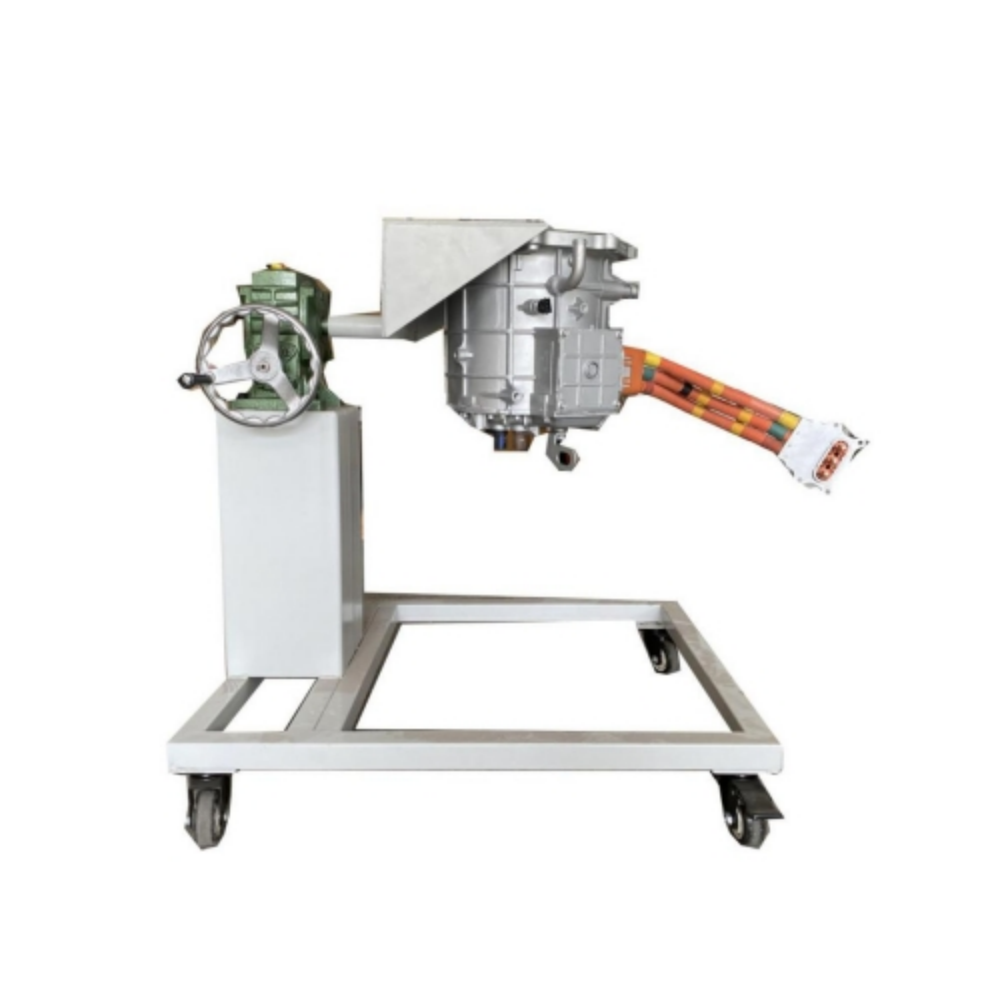
10. The system utilizes real components from a pure electric vehicle's electric drive transmission system, including a motor and controller, a single-stage transmission, electronic vacuum hydraulic braking, and transmission systems. It enables functional testing and training of the electric drive system for electric vehicles, including brake energy recovery, braking, forward movement, reverse movement, charging, interlocking, and simulated load adjustment.
11. Operating condition simulation system: The simulated load changes are switched using an adjustable tension controller, simulating different operating conditions of the electric vehicle (start, idle, constant speed, acceleration, deceleration, parking, and hill climbing, etc.).
12. Real-time monitoring and experimental training of the electric vehicle's electric drive system. The host computer software can read the changes in motor speed, voltage, current, torque, and other parameters under constant speed, acceleration, and deceleration conditions.
13. The motor controller and BMS control unit have diagnostic interfaces. The host computer software can read system data stream information and fault information, including brake switch, gear position, motor speed and voltage/current, regenerative braking current, motor temperature, motor torque, electronic throttle opening, bus voltage/current, motor controller output voltage/current, regenerative braking status, battery pack voltage, charging/discharging current, and temperature.
14. The vehicle control unit (VCU) has a diagnostic interface, allowing the host computer software to read data stream information from various systems.
15. The on-board charger, permanent magnet synchronous motor controller, electric vehicle instrument panel, VCU, and battery management module transmit information via CAN communication.
16. The multi-functional instrument panel displays real-time vehicle speed, voltage, gear position, current, battery status parameters, etc.
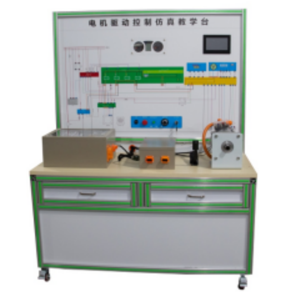
17. The panel is made of 4mm thick aluminum composite panel. The vertically mounted panel features a full-color standard system diagram printed using UV flatbed inkjet printing. Students can visually compare the diagram with the actual device to understand and analyze the system's working principle.
18. The panel is equipped with detection terminals, allowing direct testing of electrical signals of system circuit components, such as resistance, voltage, current, and frequency signals.
19. A fault simulation system is installed, enabling the setting and diagnosis of faults in low-voltage circuit systems. It can set up and assess 15 common fault points.
20. The equipment frame is constructed using two types of integrated all-aluminum alloy profiles: 40mm×40mm and 40mm×80mm. It is oil-resistant, corrosion-resistant, and easy to clean. The 40cm wide tabletop is durable and rust-free. It includes four self-locking casters for easy movement.
21. Accompanying training (experiment) manuals and other teaching materials are provided, including explanations of working principles, training projects, fault setting and analysis, and other key points.
22. Install safety protection devices: emergency stop switch, mechanical main power switch, maintenance switch, protective cover for rotating parts, high-voltage safety protection device and warning signs.
Technical Specifications:
Vehicle Dimensions: 4612 × 1852 × 1640mm (L × W × H)
Bridge Dimensions: 1740 × 600 × 1700mm (L × W × H)
Power Supply: Lithium iron phosphate battery pack
Operating Temperature: -20℃ ~ +60℃